Solar system Design and cost analysis for residential building.

DESIGN AND COST ANALYSIS OF SOLAR
POWERED SYSTEM FOR RESIDENTIAL BUILDING (2 BEDROOMS).
BY
ALA SAMUEL OLUWADAMILARE FPA/EE/18/2-0036
ANAGBA REGINALD FPA/EE/18/2-0038
SUBMITTED TO
THE DEPARTMENT OF ELECTRICAL AND
ELECTRONICS ENGINEERING
SCHOOL OF ENGINEERING
THE FEDERAL POLYTECHNIC, ADO EKITI,
EKITI STATE.
IN FULFILMENT OF THE REQUIREMENTS FOR
THE AWARD OF NATIONAL DIPLOMA (ND) IN ELECTRICAL/ELECTRONICS ENGINEERING.
JUNE,2021
CERTIFICATION
This is to certify that this project was
carried out by:
ALA SAMUEL OLUWADAMILARE FPA/EE/18/2-0036
ANAGBA REGINALD
FPA/EE/18/2-0038
Of the Department
of Electrical and Electronics Engineering of the Federal Polytechnic Ado-Ekiti,
Ekiti State, Nigeria. And it is accepted as meeting the requirement of the
award of National Diploma (ND) in Electrical and Electronics Engineering.
………………………….. ……………………………
Mr Y.
Yusuf Engr. A.A. Adebayo
Project
Supervisor HOD

External Examiner
JUNE, 2021
ABSTRACT
The need for electric energy, which is an
indispensable part of life, is increasing with each passing day in parallel to
the developments in technology. However, the fact that costs rise in meeting
these needs, and that damage is done to nature while energy is being obtained
bring clean energy sources such as solar and wind energies to the agenda. On
the other hand, the possibility that birds, though slightly, may suffer when
wind is used as a source of energy renders solar energy more
environment-friendly and important. Therefore, the use of solar panels is
increasing rapidly. Solar panels, which, with their increased power capacity,
are used in homes, country cottages, street lighting, meeting the electricity
needs of public buildings, garden lighting and irrigation systems, are
especially used in meeting the energy needs in specific remote locations. In
this study, a new approach was suggested in the selection of material to be
used in solar panel systems in residential building.
ACKNOWLEDGEMENT
Our sincere appreciation
goes to Almighty God for the gift of life, also to the department for the opportunity
given to partake in the research work.
Our sincere appreciation goes to our dear parents and guardian
for their financial support.
Our appreciation also goes to our project supervisor, he
has really taught us a lot of ways to be successful and for his encouragement,
we say thanks to him.
DEDICATION
We dedicated this report
(Design and cost analysis of solar powered system for residential building) to
the DEPARTMENT OF ELECTRICAL/ELECTRONICS ENGINEERING and
project supervisor MR. Y. YUSUF, our
parents and everyone who have in one way or the other participate in the
success of this report for their support in attaining this level of knowledge.
TABLE
OF CONTENT
Title page
Title page ………………………………………………………………………………………… i
Certification………………………………………………………………………………………
ii
Abstract…………………………………………………………………………………………….
iii
Acknowledgement…………………………………………………………………………….
iv
Dedication …………………………………………………………………………………………
v
CHAPTER ONE
1.1 INTRODUCTION..............................................................................1-2
1.2 STATEMENT OF THE PROBLEM ………………………….... 2
1.3 Aim/ Objectives of the project ……………….……………………. 2-3
1.4 Significance of the Study ……………….…………………………. 3
1.5 Scope
of the Study……………..……………………………………3-4
1.6 Limitations of Study …...…………………………………………… 4
1.7 Definition of Terms …………………………………………………. 4-6
CHAPTER
TWO: LITERATURE REVIEW
2.1 Solar
power usage in residential building ………………………………
7-8
2.2 Solar
panels …………………………………………………………. 8-12
2.3 Charge
controllers …………………………………………………... 12-13
2.4 Inverters
………………………………………………………………. 14-16
2.5 Advantages of pure sine wave inverter
..……………………………… 17
2.6 Disadvantage
of pure sine wave inverter .…………..………………….
17
2.7
Modified sine wave inverter …….………….………………………….
17-18
2.8 Battery……………………………………...……………………….…. 19-24
CHAPTER
3
3.1 Design methodology ……………………………………………………25
3.2 Study area ……………………………….……………………………… 26
3.3 A monocrystalline
solar panel ……...………………………………….... 27-30
3.4 Energy Calculations ……………..……………………………………… 30
3.5 Panel Sizing ………………………….…………………………………. 31
3.6 Battery Sizing …………………………….…………………………….. 31-32
3.7 Inverter …………………………………………………………………. 32
3.8 Charge Controller ……………………………….……………………… 32-34
3.9 Site Assessment …………………………………….……………………34-36
4.1 Load estimate of the 2 bedrooms flat …………………………………… 37
4.2 Estimating the numbers and type of solar
panel needed. ………………... 38
4.3 Battery ……………………………………………...…………….……… 38
4.4 Evaluating
Charger Controller Specifications …………………….…….. 38-39
4.5 Inverter
Specifications …………………………………………….…...... 39
4.6 Cable or interconnectors ………………………………………………… 39-40
4.7 Cost
analysis of various products and qualities ……………………….....
40
4.8 Items
recommended, Size and Uniqueness ……...……………………….
41-42
4.9 Cost estimate of
solar materials …………………………………………. 42-43
CHAPTER
5
SUMMARY
…………………………………….………………………….… 44
CONCLUSION
……………………………………………………………… 44
RECOMMENDATION ……………………………………………………… 45
REFERENCES
………………………………………………………………. 46-47
CHAPTER ONE
1.1
INTRODUCTION
The
solar radiation that reaches the earth comprises of about 50% visible light,
45% infrared radiation, small amount of ultraviolet and other forms of
electromagnetic radiation. This radiation has the potential to be converted to
either thermal or electrical energy. Solar energy can be converted directly to
electricity by solar cells. It works on the principle that in such cells, a
small electric voltage exists when light strikes the junction between a
conductor and a semi-conductor or the junction between two different
semiconductors. The potential of the solar energy therein, is enormous, about
200,000 times the world’s daily electricity generated if only it can be
harnessed. According to Adewumi, (2011), the sun generates more than 10,000
times the amount of energy the entire world consumes annually. Although, the
solar energy is free, but the high cost of its collection, conversion and
storage technologies, all hinders its exploitation.
Nigeria
is rich in energy resources such as petroleum, natural gas, coal, tar sand, and
biomass. The country has since independence used the convectional energy
sources of petroleum, natural gas and coal to generate electricity with little
or no effect in the electricity generated. These sources also impact the
atmosphere negatively with lots of green-house gasses emissions. From the
position of Nigeria in world chart, the country has a massive potential for
developing and implementing solar energy. Nigeria has an annual average daily
solar radiation of about 5.25 kWh/m²/day, varying between 3.5 kWh/m²/day at the
coastal areas and 7.0 kWh/m²/day at the northern boundary, and average sunshine
hours all over the country is about 6.5 hours Adewumi et al, (2011).
This
shows that implementing solar energy in Nigeria energy mix strategy is a great
opportunity for Nigeria to get energy (electricity) that is renewable,
sustainable, affordable as well as reducing the total dependence on fossil
fuels; and finally come out of her power inadequacy or dilemma that had persist
for decades.
1.2 STATEMENT
OF THE PROBLEM
In
Nigeria today, interrupted power supply from distribution companies has been
the norm giving everyone serious concern as it makes life difficult and
unbearable to people in different field of works; from entertainments, industries,
churches, shopping malls, schools, business center etc. who depends on power
supply for their day-to-day activities.
Some however have resorted to the use of
plants and generators to enables them meet up with their activities at the
detriments health challenges poses by the emissions of this devices to the
atmosphere. If constant and clean supply of electricity is ensured, all these
setbacks would have been avoided. This project work is intended to proffer
solution to these setbacks through cost analysis of a residential building of
electrical components/equipment requirement for solar system power usage in
Federal Polytechnic Ado-Ekiti.
1.3 Aim/
Objectives of the project
The
aim of the study is to design and costs analyze solar power system requirement
to power a residential building electrical gadget.
Objective
of the project are;
- To
identify the components needed to design a solar power system for a
residential building.
- To
determine the total power consumed by all electrical equipment in a
residential building.
- To
determine the rating and numbers each of the solar power system sets
needed in a residential building, and;
- To
determine the cost implications of the solar system design and the
installation.
1.4 Significance
of the Study
This
project “the design and construction of a solar power system for a residential
building” serves as an alternative source of electrical power supply which is
needed in our society and useful as thus;
1.
Low power cost; since solar power doesn’t requires fuel to run and it doesn’t
require much resources and cost. It provides an opportunity for anyone who is
looking to reduce monthly utility bills and make a long-term, low-risk
investment.
2.
Its renewable; sun energy is renewal source, so it give to not limited power
supply under this source.
3.
It will extend our knowledge in solar power system and how it works.
1.5 Scope
of the Study
The
scope of the project shall cover the following areas.
1.
The work will cover the selection of solar charge controller, battery and
inter-connectors (cables) based on the requirement of the system.
2.
Design analysis of the solar panels
3.
The economics analysis (bills of engineering measurement and evaluation).
4.
Testing and experimentation of the system
1.6 Limitations
of Study
Solar Energy Storage Is Expensive
Solar
energy has to be used right away, or it can be stored in large batteries. These
batteries, used in off-the-grid solar systems, can be charged during the day so
that the energy is used at night. This is a good solution for using solar
energy all day long but it is also quite expensive.
It is smarter to just use solar energy during
the day and take energy from the grid during the night (you can only do this if
your system is connected to the grid). Luckily your energy demand is usually
higher during the day so you can meet most of it with solar energy.
1.7 Definition
of Terms
- Absorbers--Dark-colored
objects that soak up heat in thermal solar collectors.
- Active
solar heater--A solar water or space-heating system that moves heated air
or water using pumps or fans.
- Alternating
current--Electric current in which the direction of flow is reversed at
frequent intervals--usually 100 or 120 times per second (50 or 60 cycles
per second or 50/60 Hz).
- Ampere
(A) or amp--The unit for the electric current; the flow of electrons. One
amp is 1 coulomb passing in one second. One amp is produced by an electric
force of 1 volt acting across a resistance of 1 ohm.
- Ampere-hour
(AH)--Quantity of electricity or measure of charge. How many amps flow or
can be provided over a one-hour period. Most batteries are rated in AH.
- Array--Any
number of photovoltaic modules connected together to provide a single
electrical output. Arrays are often designed to produce significant
amounts of electricity.
- Cell--The
basic unit of a photovoltaic panel or battery
- Cell
barrier-- A very thin region of static electric charge along the interface
of the positive and negative layers in a photovoltaic cell. The barrier
inhibits the movement of electrons from one layer to the other, so that
higher-energy electrons from one side diffuse preferentially through it in
one direction, creating a current and thus a voltage across the cell. Also
called depletion zone, cell junction, or space charge.
- Cell
junction-- The area of immediate contact between two layers (positive and
negative) of a photovoltaic cell. The junction lies at the center of the
cell barrier or depletion zone.
- Charge
controller--An electronic device which regulates the voltage applied to
the battery system from the PV array. Essential for ensuring that
batteries obtain maximum state of charge and longest life.
- Combined
collector-- A photovoltaic device or module that provides useful heat
energy in addition to electricity.
- Cycle
life--Number of discharge-charge cycles that a battery can tolerate under
specified conditions before it fails to meet specified criteria as to
performance (e.g., capacity decreases to 80-percent of the nominal
capacity).
- Direct
Current (DC)--Electric current in which electrons flow in one direction
only, opposite of alternating current.
- Discharge
rate--The rate, usually expressed in amperes or time, at which electrical
current is taken from the battery.
- Hybrid
system-- A PV system that includes other sources of electricity generation,
such as wind or fossil fuel generators.
- Interconnect--A
conductor within a module or other means of connection which provides an
electrical interconnection between the solar cells.
- Inverters--Devices
that convert dc electricity into ac electricity (single or multiphase),
either for stand-alone systems (not connected to the grid) or for
utility-interactive systems.
- Load--Anything
in an electrical circuit that, when the circuit is turned on, draws power
from that circuit.
CHAPTER
2
LITERATURE
REVIEW
2.1 Solar power usage in residential building
The
global growth of energy demand is putting pressure one stablishing regulatory
frame works aimed at reducing the carbon footprint of our societies, thus
mitigating the climate change.
For
instance, one of the main targets of the European Union’s energy policies is
the reduction of greenhouse emissions by 80-95% by 2050.
Such
decarburization process, as envisioned by most researchers and policy makers,
requires policies promoting investments to support new low-carbon solutions,
efficiency measures, and people behavioral changes.
Renewable
energies are recognized as one of the most important pillars for achieving a
more sustainable society.
A
recent report by the International Renewable Energy Agency (IRENA) indicates
that the share of renewable energy in the power sector would increase from 25%
in 2017 to 85% by 2050, mostly through growth in wind and solar power
generation.
Therefore,
greater efforts should be made to achieve a higher and widespread penetration
of renewables in all economic sectors.
In
this context, solar energy has been the subject of intense research and
development efforts thanks to its promising and unmatched resource potential,
which led to a large diffusion as residential, commercial, and industrial solar
appliance over the last few decades. Among others, buildings represent an
important sector for solar energy technologies, since they are responsible for
about 39% of the total primary energy consumption.
Therefore,
the integration of solar technologies in buildings, such as advanced solar
thermal collectors, photovoltaic (PV) and hybrid PV systems, the use of
photoactive materials, solar cooling and passive solar systems, and energy
storage, may lead to significant primary
energy savings and carbon emission
reduction. This however depends on how the house was constructed as this may or
may not be feasible as the more the radiation received during the day, the more
efficient it is when the need arises.

Figure 2.1: Solar power usage set up (https://images.app.goo.gl/
2013)
2.2 Solar panels
Solar
panels, generally comprising of arrays
of photovoltaic cells, use the solar energy directly from the sun
to generate electricity for our daily use. Being environment friendly in
nature, solar panels collect the solar energy which is available in abundance
on our planet and convert it using the advanced technology developed by human
beings. This invention of humans has led to a great achievement in world’s history
of conserving non-renewable resources and saving the planet as well as the natural
resources from depletion (Bhatia, 2014).
A collection of PV modules is called a PV
Panel, and a system of Panels is an Array. They are located on the
roof of the house and connected to the heating system. Solar panels serve two
major functions in residential buildings which are to heat water and produce
electricity. Solar panels designed to heat water are also known as thermal solar
system while electricity producing panels are called photovoltaic systems.
The method of operation depends on what
purpose the solar panels are meant to serve i.e. either as solar water heating
or for electricity. A solar water heating system usually contains a ‘collector’
to absorb solar radiation and turn it into heat. A heat-conducting liquid then
carries the heat from the collector to the hot water tank.
In an electricity-producing system
however, a positively charged layer of silicon is placed against a negatively
charged layer of silicon forming a field of electrical charges to pass through.
The sunlight as it shines on the panel creates these electric charges. A
conductive metal is made available which concentrates the charge into an
electric current which can power household appliances.
Types
of solar panel
a)
Monocrystalline
b)
Polycrystalline
c)
Thin film
2.2.1 Monocrystalline
A monocrystalline solar panel is
a solar panel comprising monocrystalline solar cells.
These cells are made
from a cylindrical silicon ingot grown from a single crystal of silicon of high purity in the same way as a
semiconductor. The cylindrical ingot is sliced into wafers forming cells.

Fig 2.2.1: Mono
crystalline panel ( https://5.imimg.com/
)
2.2.2 Poly crystalline panel
Polycrystalline solar panels are also referred to as “multi-crystalline,” or many-crystal silicon. Because there are many
crystals in each cell, there is less freedom for the electrons to move. As a result, polycrystalline solar panels have
lower efficiency ratings than monocrystalline
panels.

Fig 2.2.2: Poly crystalline panel ( https://5.imimg.com/ )
2.2.3 Thin film panels
Thin-film solar cell, type of device that is designed to convert
light energy into electrical energy (through the photovoltaic effect) and
is composed of micron-thick photon-absorbing material layers deposited over a
flexible substrate.

Fig
2.2.3: Thin film panels ( https://www.solarreviews.com/
)
2.2.4 Types of solar panels comparison
Monocrystalline
Polycrystalline
Thin-film
|
Solar panel type |
Advantages |
Disadvantages |
|
Monocrystalline |
High
efficiency/performance |
Higher costs |
|
Polycrystalline |
Low cost |
Lower efficiency/performance |
|
Thin-film |
-Portable
and flexible -Lightweight |
Lowest efficiency/performance |
https://www.energysage.com/
|
Solar panel |
Cost benefits |
Condition |
maximum lifespan |
|
Monocrystalline |
its expensive |
it’s the best |
50 years |
|
Polycrystalline |
less expensive |
its better |
30 years |
|
Thin-film |
least expensive |
not advisable |
20 years |
These are sold to consumers as separate
devices often in conjunction with solar generators for uses such as RV, boat
and off-the-grid home battery storage systems (Wikipedia, 2011a, ADEWUMI, 2011). Charge controllers are
also called solar regulators in solar application. They function majorly to
disable further current flow into batteries when they are full. Simple charge
controllers stop charging a battery when they exceed high voltage level and
re-enable charging when battery voltage drops below that level.
2.3.1 Types of solar charge
controllers
Pulse Width Modulation(PWM)
Maximum Power Point Tracking (MPPT)
Both of them are great for all
environment, but they are chosen or selected due to the solar array system
that’s to be used.
Fig
2.3.1: MPPT solar charge controller ( https://shop.orioncoreltd.com/ )

Fig
2.3.2: PWM solar charge controller ( https://encrypted-tbn0.gstatic.com/
)

2.4 Inverters
An inverter is an electrical device that
converts direct current (D.C) to alternating current (A.C). This converted A.C
can be at any required voltage and frequency with the use of appropriate
transformers, switching and control circuits (ADEWUMI et al, 2011).
A power inverter is a complex device that
converts direct current (D.C) power from solar charged battery into alternating
current (A.C) form (ADEWUMI, 2011). It has found wide application in homes and
other domestic situations. A well manufactured inverter is characterized with
high efficiency at all power levels, ruggedness to accommodate multiple
environment, stable (i.e. will not overheat) and will provide the required
power and wattage to operate small appliances (ADEWUMI et al, 2011).
2.4.1
Classes of power inverters
a. Pure
sine wave
b. Modified
sine wave
2.4.2 Pure sine wave power inverter
The output voltage of a sine-wave inverter has a sine
wave-form like the sine wave-form of the mains / utility voltage. In a sine
wave, the voltage rises and falls smoothly with a smoothly changing phase angle
and also changes its polarity instantly when it crosses 0 Volts (https://samlexamerica.com/support/f

Fig 2.4.1: Pure sine wave inverter ( https://cdn.filestackcontent.com/
)

Fig. 2.4.1: Pure sine wave form ( https://cdn.filestackcontent.com/ )
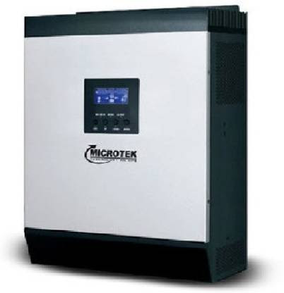
Fig 2.4.2: Modified sine wave inverter ( https://encrypted-tbn0.gstatic.com/
)

Fig. 2.4.3: Modified sine wave form
2.5
Advantages of pure sine wave inverter
i.
The
output wave-form is a sine-wave with very low harmonic distortion and clean power like utility supplied
electricity
ii.
Inductive
loads like
microwaves and motors run faster, quieter and cooler
iii.
Reduces
audible and electrical noise in fans, fluorescent lights, audio amplifiers, TV, fax
and answering machines
iv.
Prevents
crashes in computers,
weird print outs and glitches in monitors
2.6
Disadvantage of pure sine wave inverter
i.
It’s quite expensive than modified sine
wave
2.7 Modified sine wave inverter
In a modified sine wave,
the voltage rises and falls abruptly, the phase angle also changes abruptly and
it sits at 0Volts for some time before changing its polarity (https://samlexamerica.com/, 2014).
2.7.1
Advantages of modified sine wave inverter
ii.
It’s very cheap for purchase
iii.
It can be constructed easily
2.7.2
Disadvantages of modified sine wave inverter
Any device that uses a control
circuitry that senses the phase (for voltage / speed control) or instantaneous
zero voltage crossing (for timing control) will not work properly from a
voltage that has a modified sine wave-form. Also, as the modified sine wave is
a form of square wave, it is comprised of multiple sine waves of odd harmonics
(multiples) of the fundamental frequency of the modified sine wave. For
example, a 60 Hz. modified sine wave will consist of sine waves with odd
harmonic frequencies of 3rd (180 Hz), 5th (300 Hz.), 7th (420 Hz.) and so on.
The high frequency harmonic content in a modified sine wave produces enhanced
radio interference, higher heating effect in motors / microwaves and produces
overloading due to lowering of the impedance of low frequency filter capacitors
/ power factor improvement capacitors.
Some examples of devices that may
not work properly with modified sine wave and may also get damaged are given
below:
i.
Laser
printers, photocopiers, magneto-optical hard drives
ii.
The
built-in clocks in devices such as clock radios, alarm clocks, coffee makers,
bread-makers, VCR, microwave ovens etc may not keep time correctly
iii.
Output
voltage control devices like dimmers, ceiling fan / motor speed control may not
work properly (dimming / speed control may not function)
iv.
Sewing
machines with speed / microprocessor control
v.
Transformer-less
capacitive input powered devices like (i) Razors, flashlights, night-lights,
smoke detectors e t c (ii) Re-chargers for battery packs used in hand power
tools. These may get damaged.
Please check with the manufacturer of these types of devices for suitability
vi.
Devices
that use radio frequency signals carried by the AC distribution wiring
vii.
Some
new furnaces with microprocessor control / Oil burner primary controls
viii.
High
intensity discharge (HID) lamps like Metal Halide lamps. These may get damaged. Please check with the
manufacturer of these types of devices for suitability
ix. Some fluorescent lamps / light fixtures that have power factor correction capacitors. The inverter may shut down indicating overload
2.8 BATTERY
A battery is
a device consisting of one or more electrochemical cells with external
connections for powering electrical devices such as flashlights, mobile phones,
and electric cars. When a battery is
supplying electric power, its positive terminal is the cathode and its negative
terminal is the anode (https://en.wikipedia.org/ )
2.8.1a CLASSES OF BATTERY
We
have two major and additional classes of batteries, which are:
i.
Primary cell/battery
ii.
Secondary cell/battery
iii.
Fuel cells/flow cell
2.8.1b Primary cells or batteries
Primary batteries, or primary cells, can produce current
immediately on assembly. These are most commonly used in portable devices that
have low current drain, are used only intermittently, or are used well away
from an alternative power source, such as in alarm and communication circuits
where other electric power is only intermittently available. Disposable primary
cells cannot be reliably recharged, since the chemical reactions are not easily
reversible and active materials may not return to their original forms. Battery
manufacturers recommend against attempting to recharge primary cells. In
general, these have higher energy densities than rechargeable
batteries, but disposable batteries do not fare well under high-drain
applications with loads under 75 ohms (75 Ω). Common types
of disposable batteries include zinc–carbon batteries and alkaline batteries.

Fig.
2.8.1: Primary cell (https://d3jlfsfsyc6yvi.cloudfront.net/
)
2.8.2a Secondary cells/battery
Secondary batteries,
also known as secondary cells,
or rechargeable batteries,
must be charged before first use; they are usually assembled with active
materials in the discharged state. Rechargeable batteries are recharged by
applying electric current, which reverses the chemical reactions that occur
during discharge/use. Devices to supply the appropriate current are called
chargers.
The oldest form of
rechargeable battery is the lead–acid
battery, which are widely used in automotive and boating applications.
This technology contains liquid electrolyte in an unsealed container, requiring
that the battery be kept upright and the area be well ventilated to ensure safe
dispersal of the hydrogen gas
it produces during overcharging. The lead–acid battery is relatively heavy for
the amount of electrical energy it can supply. Its low manufacturing cost and
its high surge current levels make it common where its capacity (over
approximately 10 Ah) is more important than weight and handling issues. A
common application is the modern car
battery, which can, in general, deliver a peak current of 450 ampere
The sealed valve regulated lead acid battery (VRLA
battery) is popular in the automotive industry as a replacement for the lead–acid
wet cell. The VRLA battery uses an immobilized sulfuric acid electrolyte, reducing the chance of leakage and
extending shelf life.

Fig. 2.8.3: (https://chem.libretexts.org/)
2.8.2b Types of secondary cell/battery
i Gel batteries (or
"gel cell") use a semi-solid electrolyte.
ii Absorbed Glass Mat (AGM)
batteries absorb the electrolyte in a special fiberglass
matting
iii Tubular battery
iv Aluminum-ion
battery
2.8.3 Fuel cell/flow battery
This type uses hydrogen-oxygen as fuel

Fig 2.8.4: (https://lh3.googleusercontent.com/
2.8.4 Tubular
battery
These
are batteries that have bigger positive lead internally, which help them to
withstand high temperature and have longer life than any other battery.
Fig. 2.8.5: Tubular
battery: ( https://5.imimg.com/
)
2.8.5 Advantages
of tubular battery
1. Tubular
batteries last longer for 5 to 15 years under proper maintenance
condition.
2. Highly reliable compared to normal flat plate batteries.
3. The spine of Tubular Batteries
are made using High pressure HADI
casting method which ensures long life even under heavy temperature
and rough usage.
4. Perform consistently under any conditions hence suitable
for sensitive and heavy applications.
5. Faster charging is one the notable feature in Tubular
batteries.
6. Low
maintenance – No need to top-up with distilled
water frequently.
7. Long Standby life compared to flat pasted plate
batteries.
8. Recommended for UPS
inverters (https://upsinverterinfo.com/ )
2.8.6 Tubular battery products
Eastman
Fig
2.8.6: https://kara.com.ng/
Luminous
Fig.
2.8.7: https://www-konga-com-
These
batteries are very strong and useful for UPS inverters i.e. uninterrupted power
supply, they have much run time, still the best affordable battery.
CHAPTER 3
For the purpose of this
study, information was gathered both from the primary and secondary sources of
information with more of the information obtained from the secondary sources.
The secondary sources include: existing records and documentation in books,
journals, web materials and other literatures. Information obtained was
analyzed using the cost-benefit analysis
|
DB (Distribution Board) |
|
Power inverter |
|
Photovoltaic cell |
|
Solar charge controller |
|
Battery bank |
|
AC loads |
|
DC loads |
Fig. 3.1: Block diagram
of solar installation
3.2 Study area
The
Federal Polytechnic Ado-Ekiti (7° 35′ 34.54″ N, 5° 17′ 30.92″ E)
(Wikipedia)
Fig 3.2 Yearly
sunshine hours from 2010-2021 (https://www.worldweatheronline.com/)
These
are the proofs that it’s profitable to use solar system in this area of the
country.
There
are two distinct seasons: the rainy season which starts in April and peaks in
June through September and the dry season which begins in November and lasts
till April.
So,
throughout the dry season here in the part of the country, even during raining
season, we still have as much sun as possible.
In this project, we are going to be making use of monocrystalline solar
panel, because of it features.
3.3 A monocrystalline solar panel is a
solar panel comprising monocrystalline solar cells.
These cells are made from a cylindrical
silicon ingot grown from a single crystal of silicon of high purity in the same
way as a semiconductor.
The cylindrical ingot is sliced into wafers
forming cells. To maximize the utility of the
Cells, the
circular wafers are wire cut to an octagonal shaped wafer.
These cells have a
unique look because of the octagonal shape. These cells also have a uniform
colour.
3.3.1 How do Monocrystalline Solar Panels work?
When sunlight
falls on the monocrystalline solar panel the cells absorb the energy
and through a
complicated process create an electric field. This electric field comprises
voltage and current and generates power which is governed by the equation P
(power) = V (voltage) x I (current). This power can be used directly to power
devices that run on direct current (DC). This power can also be converted to
alternating current (AC) using an inverter.
3.3.2 Features of monocrystalline solar panels
Monocrystalline
solar cells are among the three types of materials that exhibit photovoltaic
properties.
The other two are
polycrystalline solar cells and amorphous or thin film solar panels.
Monocrystalline solar panels have features considered better than the other two
types of panels. They are as follows:
These cells in the
panel have a pyramid pattern which offers a larger surface area to collect more
energy from the sun’s rays.
The top surface is
diffused with phosphorous which helps to create an orientation that is
electrically negative as compared to the bottom which has a positive electrical
orientation, which in turn helps to create the electric field.
To reduce
reflection and thereby increase absorption, the cells are coated with silicon
nitride.
The produced
electricity is collected through metal conductors printed onto the cells.
Because of the
above features, the main advantage of monocrystalline solar cells is the higher
efficiency of conversion of solar energy into electric energy than its two
other counterparts.
These panels have
longevity up to 30 years. It’s exhibit greater heat resistance.
(https://economictimes.indiatimes.com/,(May 02, 2019).
3.3.3 Tilt
angle: Tilt angle is the setting of the panels one needs to have to get the
maximum radiance. Ideally the tilt angle is the latitude of the geographic
location. It is suggested to have an adjustable panel frames as the sun hours
keep changing with respect to the tilt in raining and dry season. Hence for any
area a specific tilt angle is calculated to get the maximum radiance throughout
the year for a fixed panel. Also, it is advised to have the panels facing the
south to get the maximum afternoon sun. A couple of devices are used in the
process of finding the tilt angle and the radiance that will fall upon panel at
that tilt angle are inclinometer and pyranometer, respectively. An inclinometer
is kept on the panel and the degrees are read to find the latitude of the area
as it is perpendicular to the Sun’s radiations when it is at its highest point
in the sky. Pyranometer measures the solar irradiance that will fall at a given
tilt angle. It measures solar irradiance in Watts per meter Sq. (W/m^2).
It is quite important to
consider the tilt angle of our solar panels because it is going to determine
the amount of sun ray falling on the solar panels during the day, proper tilt
angle helps collect the maximum sunray (energy) during the day.
The optimum tilt angle is calculated by adding 15 degrees to
our latitude during cloudy season and subtracting 15 degrees from your latitude
during sunny season. Our latitude is 9.042290°, the optimum tilt angle for our
solar panels during cloudy season will be9.042290 + 15 = 24°. The sunny season
optimum tilt angle on the other hand will be 9.042290 – 15 = -5.96°.
Fig. 3.3: Pyranometer
Fig. 3.3.1: Pyrheliometer
Fig
3.3.2 Internal arrangement of
pyranometer and pyrheliometer
3.4 Energy
Calculations: The consensus is to add wattage of the
equipment that are going to be powered using the PV system. Alternatively, for
this task we can use baseload calculators that are available on the internet.
But we have used our normal calculator to calculate the baseload of our
project, every device has fixed power consumption that can be found on its name
plate details. This data is retrieved from all the devices that are going to be
used. Other data entered is number of each appliance that are going to be used
and number of hours the appliance is supposed to remain ON, for this project,
it is going to power the loads for 14 hours. Another point one must pay attention
to is the system voltage. It is required that the system level chosen before we
further probe into designing. Subsequent equipment designing would be based on
the system voltage level. For this project, we will make use of 24volt system.
3.5 Panel Sizing:
Once the total load to be energized using the PV system is calculated we must
find out what area of solar panels would be required to generate that much
amount of power. It is an inherent property of any panel to have internal
losses. This factor should be kept in mind. As in the energy calculation we
have already found the total watt-hours, for finding the wattage of panels that
would be required we need to divide the total watt-hours with peak sun hours. Another
useful tool that can be used is PV WATTS that helps use to calculate panel
sizing just by putting the parameters such as energy consumption, tilt angle,
and Sun hour.
To
calculate the number of solar panels needed for this two bedrooms flat solar installation, here are the calculations:
Total
value of load to be powered = 1,813
watts
Total
lighting hours needed per day, 6
hours during day time and 6 hours at
night = 12 hours
Total
number panel capacity needed = 1,819 ×
12 = 21,828watt hours
Considering
the worst weather at raining season, we’ll have 8 hours of sunshine each day.
Therefore,
21,828 watthour ÷ 12 hours = 1819watt solar panel, since this may
not be available, we will make use of 8 pieces of 250 watts/12v solar panels in parallel arrangement.
3.6 Battery Sizing:
PV battery system assesses various strategies from a financial perspective. The
valuable existence of the battery is limited to 5,000 cycles or in the planned
living time of 20 years. The maintenance of photovoltaic and rechargeable
annual activities and expenditure systems is set at 1.5% per the speculative
cost. Assume that the cost system for the battery and PV is comparable to their
size. Following is a formula that will enable to calculate what size of battery
they should have. Since we are using 12v battery, the total capacity of battery
required to serve the load in all condition is:
21828WH ÷ 12v =1819A,
1819A/60min=30.32A for an hour, 30.32×12 hours=363.8 approximately
400AH since this capacity is not
available in the market, we will use 2 pieces of 200 AH battery for this design.
3.7 Inverter:
Inverter deals with following main tasks of energy:
a. Convert
DC from PV module to AC
b. Ensure
that the cycle of alternating current cycles is 50 cycles
c. Reduce voltage variations
d. Ensure
that the condition of the AC waveform is suitable for the application most
system-connected inverters can be introduced externally, and most of the
off-grid inverters are not weather-resistant. There are basically two types of
grid intelligent Inverters: Those designed for batteries and those designed for
systems without battery-connected inverter systems and give excellent
void-quality strength. For matrix associations, the inverter should have a
"useful-interactive" typeface, which is printed specifically for the
publication name
Grid-connected
systems measure the power of extracting PV clusters rather than a bunch of
prerequisite buildings. It asserts that what each power supply needs are what
the matrix-related PV system can give naturally is drawn from the net.
Invertors used for solar PV systems are usually based upon the total wattage of
the solar panels, as the invertor will be continuously converting the power
generated.
The
second consideration one must investigate, is the voltage level of the system.
For example, if the system is designed to generate 2000 Watts at a voltage
level of 12 V then the invertor selected should be rated 12V, 2000 Watts. In
this project, we make use of 2500VA/12v inverter.
3.8 Charge
Controller: The charge controller, sometimes referred
to as a photovoltaic controller or charger, is only necessary for the system
which involves a battery. The basic function of charge controller is to monitor
charging and discharging of the battery. It prevents the battery from being
completely charged or discharged. This is important because over charging can
lead to destruction of the battery and under charging decreases the battery
life. Another important reason to use a charge controller is to prevent a
reverse current flowing from battery to the system. There are two types of
controllers that are widely available in the market;
a.
Pulse width Modulation (PWM),
b.
Maximum Power Point Tracking (MPPT)
3.8.1 Pulse
width modulation: A pulse width modulation charge controller is set match
the input power of the battery irrespective of the power generated by the
panels. There is an inherent loss in power observed in this type of charger.
3.8.2 Maximum
Power Point Tracking (MPPT): This type of charger
helps to get the optimum charging power for any given point of time and offers
better efficiency than PWM. Though the MPPT charge controllers enable you to
have better efficiencies and provides more power than compared to PWM for similar
condition, the main cause of not opting for MPPT is price of it. MPPT charge
controllers are more expensive than PWM controllers. Keeping this parameter in
mind, this project will be using a MPPT charge controller for realizing the
concept. To select the size of charge controller one must know the voltage
level of the system and the maximum operating current. It is a usual practice
to oversize the controller for safety reasons.
3.8.3 Calculating the size of solar charge
controller needed:
To do this, we need the below parameters:
·
Power rating of solar panel
·
Voltage rating of solar panel
Power rating of solar panel is 250 watt × 8
pieces of solar panel = 2000 watt
Therefore 2000 watt ÷ 12 volt = 166.6 Amps
approximately 167 Amps/12v/24v/48v solar charge controller.
Here
are the site specifications;
External
dimension: length-20.2meter, Breadth-14.7 meters
Fig
3.9 Load
estimate
|
Loads |
Unit power rating(watts) |
Quantity |
Cumulative
Power |
|
Lamps |
5 |
20 pieces |
100 watts |
|
Ceiling fan |
60 |
2 sets |
120 watts |
|
A/c |
746 |
1 set |
746(1 hp) watt |
|
Washing machine |
150 |
1 |
150 watts |
|
Pressing iron |
300 |
1 |
300 watts |
|
Water heater |
150 |
1 |
150 watts |
|
Freezer |
120 |
1 |
120 watts |
|
Tv set |
35 watts |
3 |
103 watts |
|
Electric blender |
30 |
1 |
30 watts |
|
Total |
|
|
1819 watts |
We have maximum of 20
lamps to be switched on at a time in the building for the purpose of energy
saving.
Other specifications will
be found in chapter 4 or this report.
Fig
3.9.1 Standard
2 bedrooms bungalow.
CHAPTER
4
4.1 Load estimate of the 2 bedrooms flat
For
a standard 2 bedroom flat, here are the load expected:
|
Loads |
Unit power rating(watts) |
Quantity |
Cumulative
Power |
|
Lamps |
5 |
20 pieces |
100 watts |
|
Ceiling fan |
60 |
2 sets |
120 watts |
|
A/c |
746 |
1 set |
746(1 hp) watt |
|
Washing machine |
150 |
1 |
150 watts |
|
Pressing iron |
300 |
1 |
300 watts |
|
Water heater |
150 |
1 |
150 watts |
|
Freezer |
120 |
1 |
120 watts |
|
Tv set |
35 watts |
3 |
103 watts |
|
Electric blender |
30 |
1 |
30 watts |
|
|
|
Total |
1819 watts |
4.2 Estimating the numbers and type of solar
panel needed
According
to chapter 2, monocrystalline solar
panel is the best in the sense that, it can spend longer years, in that case it
requires low maintenance, it also has efficiency in radiation reception and
conversion.
To
calculate the number of solar panels needed for this two bedrooms flat solar installation, here are the
calculations:
Total
value of load to be powered = 1,813 watts
Total
lighting hours needed per day, 6 hours during day time and 6 hours at night = 12
hours
Total
number panel capacity needed = 1,819 × 12 = 21,828watt hours
Considering
the worst weather at raining season, we’ll have 8 hours of sunshine each day.
Therefore,
21,828 watthour ÷ 12 hours = 1819watt solar panel, since this may not be
available, we will make use of 8 pieces of
250 watts/12v solar panels in parallel arrangement.
4.3 Battery
For
good quality sake, we’ll make use of either Eastman 200AH/12v or Luminous
200AH/12v battery.
4.3.1 Calculating battery capacity needed
Since
we are using 12v battery, the total capacity of battery required to serve the
load in all condition is:
21828WH
÷ 12 =1819 A, 1819÷60 min=30.32A for an hour, 30.32×12 hours=363.8 ~ 400
AH since this capacity is not available in the market, we will use 2 pieces of
200 AH battery.
4.4 Evaluating Charger Controller
Specifications
Both MPPT and PWM charge controller is okay
for charging, but for current sake were going to be making use of MPPT solar
charge controller
Fig 4.4 MPPT solar charge
controller
4.4.1 Calculating the size of solar charge
controller needed:
To
do this, we need the below parameters:
·
Power rating of solar panel
·
Voltage rating of solar panel
Power
rating of solar panel is 250 watt × 8 pieces of solar panel = 2000 watt.
Therefore
2000 watt ÷ 12 volt = 166.6 ~ 167 Amps /12v/24v/48v solar charge
controller.
4.5 Inverter Specifications
Since
we already know the total load wattage, then we can conclude on the size of
power inverter to use in this project, which is 2500VA or 2000watt.
Input
and output voltage = 12v/230v
4.6 Cable or interconnectors
As
we know, DC carries much current due to low voltage supply i.e. the lower the
voltage, the more the current, also the bigger the current path, the lower it
resistance, i.e. the bigger the cable size, the more the current supplied per
time, as applicable to this project, the bigger the cable the lesser time it
takes to charge battery the same applicable to PV, the more it capacity, the
faster it takes to charge the battery.
In
this project the minimum cable or interconnector to be used in charging the
battery from the PV to solar charge controller and from solar charge controller
to battery must not be less than 6mm2 for the sake of enough current
supply to the battery.
4.7 Cost analysis of various products and
qualities
|
Items |
Products or brands |
Type |
Size |
( |
|
Battery |
Eastman |
Tubular |
200AH/12v |
120,000 |
|
|
Luminous |
Tubular |
200AH/12v |
150,000 |
|
|
Felicity |
Gel |
200AH/12v |
98,000 |
|
Power inverter |
Prag |
Pure sine wave |
3kva/24v |
158,000 |
|
|
Luminous |
Pure sine wave |
3kva/24v |
209,000 |
|
|
Felicity |
Pure sine wave |
3.2kva/24v |
|
|
|
Famicare |
Pure sine wave |
3.5kva/24v |
120,000 |
|
Solar charge controller |
Prag |
MPPT |
200A |
|
|
|
Luminous |
MPPT |
200A |
|
|
|
Felicity |
MPPT |
200A |
|
|
Solar panels |
G power |
Monocrystalline |
150W |
|
|
|
SS power |
Monocrystalline |
150W |
|
4.8 Items recommended, Size and Uniqueness
|
ITEM |
SIZE |
BRAND |
UNIQUENESS |
|
Battery |
200AH/12V |
Eastman |
- It’s quite cheap compared to lithium battery - it’s far stronger than gel battery - it has spin type positive lead which makes it have
low resistance and thereby lasts longer, since it won’t get hot easily. |
|
Power Inverter |
3KVA/12VDC/230VAC/100ADC |
Prag |
- It’s always rated lesser than it nominal power rating,
which makes not to be overloaded and then it lasts longer. |
|
Solar charge controller |
100A/12VDC/24VDC |
MPPT |
- It doesn’t waste energy - It is rugged - It can handle(control) excess current |
|
Solar panels |
150watts/12VDC |
Monocrystalline |
- it can spend longer
years, in that case - it require low
maintenance, - it also has
efficiency in radiation reception and conversion. |
4.9 Cost
estimate of solar materials
|
ITEMS Date:04/04/2021 |
Unit PRICE IN ( |
Quantity needed |
Cumulative price( |
|
250W Monocrystalline PV |
40,000 |
8 pieces |
320,000 |
|
Eastman 200AH battery |
120,000 |
2 pieces |
240,000 |
|
MPPT Solar charge
controller |
150,000 |
1 set |
150,000 |
|
2500VA power inverter
(Prag) |
180,000 |
1 set |
180,000 |
|
|
|
Total= |
|
SUMMARY
This report aimed at
Designing and cost analyzing solar powered system for residential building
(standard 2 bedrooms flat).
Introduction to this
design can be found in chapter 1, literature review in chapter 2, methodology
in chapter 3, the design load and cost analysis in chapter 4 and finally;
conclusion and recommendations in chapter 5 below.
There is a cost
associated with electrifying houses in rural areas that increases with distance
between the grid and the houses. Such instances where the cost of
electrification becomes enormously highly one can always use an off-grid PV
system. Both type of systems grid tied and off-grid PV systems have their own
advantages and disadvantages. Depending solely on the need one can decide what
they would want to go for. The trend that one can observe is that the grid-tied
system is mostly found in urban and sub-urban setting where electrification of
the area has already been achieved. The off-grid system is more suited to areas
where the electrification is yet to be accomplished.
This paper provides the
design of on and off grid solar system for a standard 2 bedroom flat.
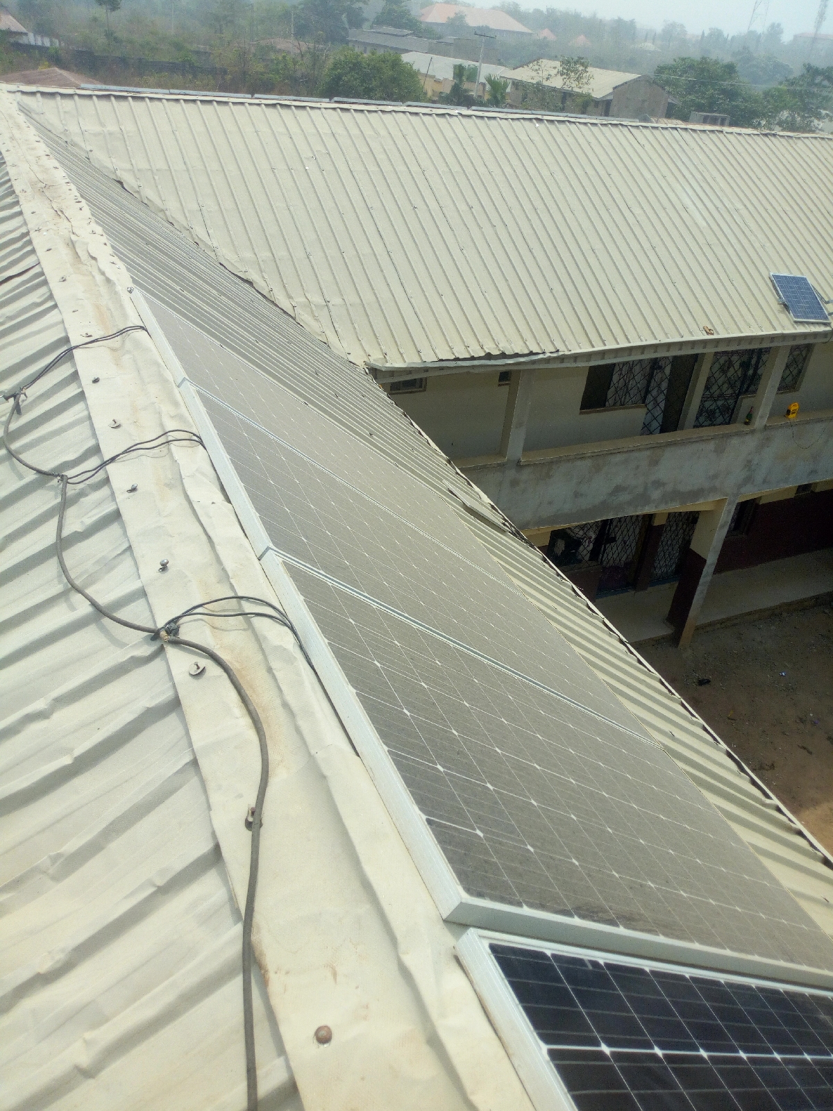
RECOMMENDATION
It is recommended that
the number of the solar panels be divided into two and tilted at both side to
avoid stress due to below reason and to save cost;
It is quite important to
consider the tilt angle of our solar panels because it is going to determine
the amount of sun ray falling on the solar panels during the day, proper tilt
angle helps collect the maximum sunray (energy) during the day.
The optimum tilt angle is calculated by adding 15 degrees to
our latitude during cloudy season and subtracting 15 degrees from your latitude
during sunny season. Our latitude is 9.042290°, the optimum tilt angle for our
solar panels during cloudy season will be9.042290 + 15 = 24°. The sunny season
optimum tilt angle on the other hand will be 9.042290 – 15 = -5.96°.
We can as well those panels face the south for maximum reception of
energy during the day.
REFERENCES
Adewumi, A.S & O.O. Ogunsote. (2011). Cost-benefit Analysis of
Solar Power
usage in Residential Buildings in Akure Nigeria. International Journal of
Building Pathology
and Adaptation. Pp.1-6. Retrieved May
28, 2021
from https://scholar.google.com/
Bhatia,
S.C. (2014). Advanced Renewable Energy
Systems. (1st ed.). WPI
Publishing. doi b18242. Pp 28. Retrieved June
5, 2021 from
https://doi.org/10.1201/b18242.
Mattia, D. R., Paolo, C., Yasser, M., & Vincenzo,
B. (2019). Advanced Solar
Technologies in
Buildings. International
Journal of Photoenergy. Vol.
2019.
Pp.1-2.doi:1709375.
Retrieved June 5, 2021 from https://doi.org/10.1155/2019/1709375.
Solar
power usage image set up. Retrieved June 6, 2021
from https://images.app.goo.gl/
Mono crystalline solar panel image. Retrieved June 6, 2021 from https://5.imimg.com/
Poly crystalline solar panel image. Retrieved June 6, 2021 from https://5.imimg.com/
Thin film panels image. Retrieved June 6, 2021 from https://www.solarreviews.com/
MPPT solar charge controller. Retrieved June 6, 2021 from https://shop.orioncoreltd.com/
PWM solar charge controller. Retrieved June 6, 2021 from https://encrypted-tbn0.gstatic.com/
Pure sine wave inverter. Retrieved June 6, 2021 from
https://samlexamerica.com/support/faqs/faq02.aspx
Pure sine wave inverter
image. Retrieved June 6, 2021 from https://cdn.filestackcontent.com/
Pure sine wave form. Retrieved
June 6, 2021 from https://cdn.filestackcontent.com/
Modified sine wave inverter. Retrieved June 6, 2021 from https://samlexamerica.com/.
Modified sine wave
inverter image. Retrieved June 6, 2021 from
https://encrypted-tbn0.gstatic.com/
Battery Retrieved. June 6, 2021 from https://en.wikipedia.org/
Primary cell Retrieved
June 6, 2021 from https://d3jlfsfsyc6yvi.cloudfront.net/
Secondary
cells or battery image. Retrieved June 6, 2021
from https://chem.libretexts.org/
Fuel cell image Retrieved June 6, 2021 from https://lh3.googleusercontent.com/
Tubular battery exploded diagram Retrieved
June 6, 2021 from https://5.imimg.com/
Yearly sunshine hours from 2010-2021. Retrieved June 6, 2021 from
https://www.worldweatheronline.com/
Features of monocrystalline solar panel Retrieved June 6, 2021 from
https://economictimes.indiatimes.com/.

Comments